Developments in Virtual 3D Imaging of Cultural Artefacts
The collapsable, portable electromechanical Virtual 3D (V3D) Object Rig Model 1 (ORm1) (Figures 1, 2, 3) was developed to meet an obvious need found after an important Australian cultural artefact - a nineteenth-century post-mortem plaster head-cast of the notorious bushranger Ned Kelly [1] - was Apple QTVR-imaged (QuickTime Virtual Reality) using a large static object rig at the University of Melbourne over 2003/4. The author requested that this moving and hyperlinked image be constructed as a multimedia component of a conjectured cross-disciplinary undergraduate teaching unit. The difficulties encountered in obtaining permission from the cultural collection involved to transport this object some 400 metres to the imaging rig located on the same geographical campus suggested to the author that a portable object imaging rig could be devised and taken to any cultural collection anywhere to image objects in situ.
In the early to mid-19th century these physical records were taken for phrenological research purposes, however by the late-C19 this quasi-science had been largely discredited. The underlying reasons for these practices had been forgotten; the recording and keeping was absorbed by reason of habit into accepted routine procedure; as just a part of the workflow within the State criminal justice execution process. This procedure would be rejected out of hand nowadays, but this 19th century habit of retaining physical artefacts is fortunate for the present-day cross-disciplinary historian.
As mentioned, the author wished to use the head cast as the pivotal focus for cross-disciplinary undergraduate teaching purposes with contributions from the perspective of History of Science, Australian Colonial History, Sociology and Criminology. It was considered by the subject contributors that such a cross-disciplinary teaching module could well benefit from a Web-based multimedia approach.
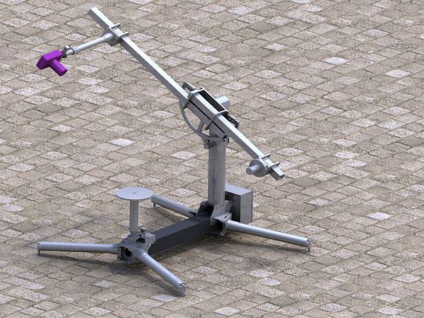
Figure 1: The Virtual 3D (V3D) Object Rig Model 1 (ORm1)
The V3D digital representation of this focal artefact, together with the ability to hot-spot salient loci of interest (and hyperlink to more detailed information) on the surface of the 3D representation was the most important criterion for all subject contributors. The known and proven technique of user-manipulable computer screen-based V3D/QTVR, derived by using a digital camera mounted on a mechanical rotatable object rig with V3D image creation using QTVR 'stitching' software, was the only feasible means, at the time, to achieve this objective.
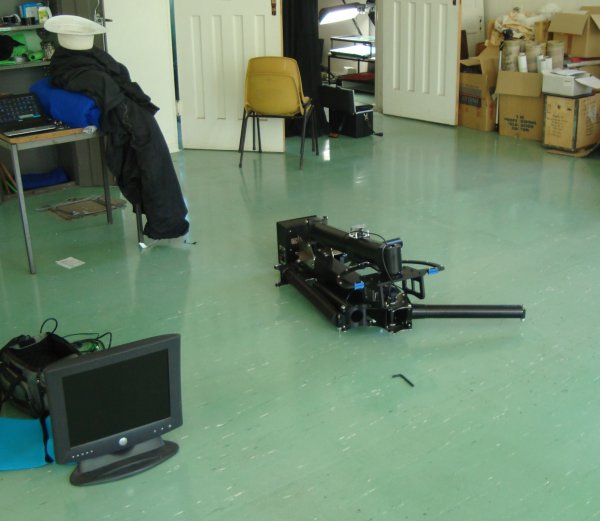
Figure 2: Virtual 3D (V3D) Object Rig Model 1 (ORm1) ready to assemble
For background information, real and simulated 3D visual experience in humans (and other animals) exploits biologically evolved mechanisms of monocular and binocular visual processing conducted in stages along the visual pathway within their brain [2]. The simulated 3D visual experience, whether artificially or photographically visualised, also involves (to varying extents) immersion in the experience partly by commanding brain-mediated attention.

Figure 3: Virtual 3D (V3D) Object Rig Model 1 (ORm1) assembled
Developing the Rig
Most V3D digital photographic object rigs developed since the early 1990s including the one example available in 2003/4 at the University of Melbourne, are large-scale static rigs requiring reticulated electrical power and surrounded by even larger amounts of physical space (at least 5x5x5m) to allow for the servicing of mounted artefacts and rig maintenance access. Since most of the artefacts of interest located within geographically widely distributed institutional collections, or in-field, it became obvious that there was a need for a portable, self-contained photographic object rig to be taken to objects, rather than vice versa.
Funding was obtained from the Helen Macpherson Smith Trust [3] and the Rig was designed using SolidWorks CAD software by Eric Huwald, La Trobe University Department of Physics, in conjunction with the author. Rig motion is controlled by Galil software [4] running on a networked (RJ-45 cable) Windows XP laptop computer using a LabVIEW [5] user interface. The aluminium structural components were machined by Whiteforest Engineering (Bundoora, Victoria) and assembled, together with the integration of electronic and DC motor movement control, by Mechanical and Mechatronics students in the University of Melbourne Department of Engineering as part of a final (fourth-year) undergraduate project ending in late 2008. I have found that employing student teams has advantages for some university projects: labour costs are reduced and mandatory subject deadlines mean that projects are invariably completed on time (albeit within a nine-month project duration)!
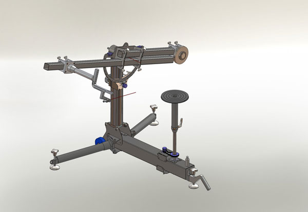
Figure 4: Schematic: Virtual 3D Object Rig model 2 (ORm2). Virtual image created using SolidWorks CAD software
After preliminary testing, which indicated that the Rig easily performed as specified within the limits of the design criteria, the ORm1 has been used, on a regular basis, within the Australian Institute of Archaeology (AIA) [6] for further testing and to image some of the thousands of Near-East artefacts held in their collections. The original ad hoc workflow has been closely analysed over time and improvements have been made in an incremental manner over the last 18 months. The process of doing so has led the team to the decision to construct an improved Model 2 (ORm2) (Figure 4) entirely within the La Trobe University Department of Physics and to retrofit as many improvements as possible to ORm1. Funding for ORm2 was provided by the Victorian eResearch Strategic Initiative (VeRSI) [7] and the La Trobe University eResearch Office [8], both of which had been made aware of the Rig after its construction in 2008 and of its potential imaging uses. They have since closely followed the Rig's development.
It is interesting to note the construction cost of ORm2, although it incorporates more advanced features, has been approximately two-thirds that of ORm1. We attribute this significant cost-saving to experience gained in the actual construction process and regular use in an institutional setting. We cannot see that all the improvements discovered heuristically could have been modelled beforehand.

Figure 5: Rig GUI (graphical user interface)
Basic Photographic Workflow
The use of these QTVR-type object rigs is not new, but an examination of these well-known workflow elements might illuminate how efficiencies have been discovered. As with most other QTVR-type object rigs, the artefact is mounted on a horizontal rotating platter with a camera moving over it in the (vertical) perpendicular plane. Rotational movement in each plane is controlled independently in previously selected radial increments. The selection of degree increment defines the number of stop points at which the camera shutter is automatically activated. Motion control software is activated by a modified LabVIEW user interface (Figure 5). The DC motors are capable of accurately moving the physical Rig elements in less than 0.1 degree increments; but in practice, 5-degree increments are used to allow acceptably smooth virtual object movement, while keeping the number of individual images within reasonable limits.
As the platter rotates, the camera arm moves over the artefact in degree increments pausing for shutter activation at each stop-point. A 360-degree horizontal platter rotation combined with a 90-degree camera movement in 5-degree increments results in 1,296 individual images. These separate images are stitched together and hotspots are inserted and hyperlinked using the software described below and the resulting fully user-manipulable (rotate, zoom, activate hotspots) .MOV QTVR file is displayed on a computer monitor. Background and artefact mounts are removed from each image using image processing software (GIMP/Photoshop). The images are stitched together using Object 2VR software [9] as single-row (V2.5D) or multi-row (V3D) moving images. Virtual artefact movement within the .MOV image is user-controlled by mouse-over command or else it can be auto-rotated.
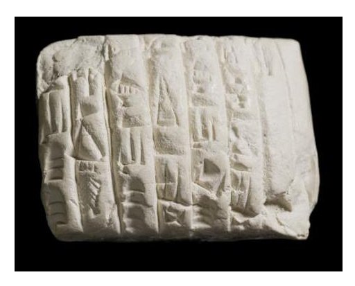
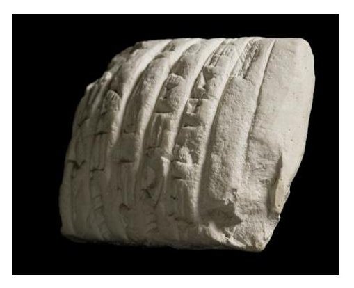
Figure 6: Cuneiform tablet (Ur-III, Babylon, ca. 2000 BC): stills of rotating .mov file (QTVR software required.)
Model 1 Workflow Experience
Having imaged a cuneiform tablet (Ur-III, Babylon, ca. 2000 BC, see Figure 6) and a shabti (Egypt, New Kingdom, 1700-1200 BC, see Figure 7 (this interim step in the imaging workflow illustrates the result of not removing the background)) many times for testing purposes, we found that the total time to image each artefact amounted to tens of hours, and that the object mounting and scanning processes consumed around four hours, and the image processing the rest.
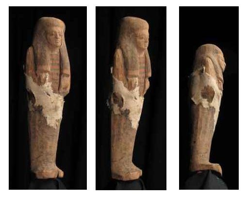
Figure 7: A shabti (Egypt, New Kingdom, 1700-1200 BC): stills displaying angles of virtual manipulation taken from manipulable .mov file (QTVR software required, download can be slow.)
We were therefore in a position to attempt to identify the most time-consuming workflow elements. The advantages of having a researcher working with an eResearch (eScience) expert group (VeRSI) became evident in the workflow analysis. Individual steps, and the decision processes within them were perceived to be:
Artefact Selection
More cubic or spherical objects produce more useful and satisfying V3D results using the V3DOR. Relatively 'flatter' artefacts, ie those having a relatively broad surface in relation to depth (eg parchment, papyrii, coins), are better V3D-imaged using devices, for example, such as polynomial texture mapping (PTM) dome such as that developed at Wessex Archaeology [10], although both sides cannot be scanned in one pass. We are currently constructing a 1-metre diameter PTM dome with visible, infra-red (IR) and ultra-violet (UV) illumination for flatter artefacts.
Artefact Mounting/Positioning
Categories of shape can be made and an array of generic acrylic and wire mounts pre-constructed to reduce mounting time. The less the intrusion, even of transparent mounts, into the visible object area, the better, as mounts must be removed using image processing software. Positioning of the artefact around centre of rotation on platter, if not correctly performed, leads to apparent oscillation of the rotating object image around the centre of rotation.
Camera Selection
The camera shutter, at the minimum of all camera functions, needs to be remote-controllable, either by electric cable or by wireless control. Good imaging results have been obtained with Canon G10 and Canon G11 compact digital cameras. A Nikon D90 DSLR has produced higher resolution images for specific artefacts and purposes. Optimal lens selection is complex to determine theoretically and has been found to be best based on empirical trials. Further improvements in digital camera technology are being incorporated as project time and funding permits.
Background Colour Selection
Differently coloured backgrounds have been trialled to shorten image processing time. A matte-black background did not contrast sufficiently with shadows on the object to enable the paint bucket (or similar) tool to be used effectively. The same applied to a blue chromakey cloth - again too dark and colour-similar. We are currently using a lime-green background, a relatively unusual colour on artefacts. Consequently it enables much of the background-elimination image processing to be semi-automated by colour-based batch processing.
Image Repositories
The linking of discoverable metadata to image files and the presentation of images in a searchable image repository are being currently developed as a new VeRSI project in conjunction with La Trobe University and the University of Melbourne. The V3DOR Group has been involved in defining the project specifications and is involved in on-going project development. Investigation of the Fedora object model is among the options for use, as well as consideration being given to the Madison Digital Image Database (MDID3) as a means of managing the digital media files and integrating them into the teaching, learning and research processes of host institutions.
Improvements Incorporated in ORm2
By implication from the above workflow descriptions, these improvements might be self-explanatory in terms of time-efficiencies:
- tripodal vs. quadripedal design is 10 Kg lighter whilst maintaining optimum rigidity and stability. Tripodal design also reduces Rig set-up time.
- improved arm length, platter height and camera location adjustment
- self-contained wheels and handles for ease of translocation within institutions
- in-built spirit levels and more rapid mechanism for rig levelling
- more compact – ORm2 was specifically designed to fit in the boot of a 1984 Toyota Corolla (an example of a quite small motor car), and easily fits into medium-size Mitsubishi and larger motor cars/vans (Figure 8)
- 2-axis laser object positioning (around object centre of rotation) on platter
- wireless remote control for Rig and camera function – removes visual obstructions and trip hazards from the vicinity of the workspace
The result of the workflow efficiencies attempted is that total object imaging time even for unknown artefacts is now 3 hours and is reducing further day by day!
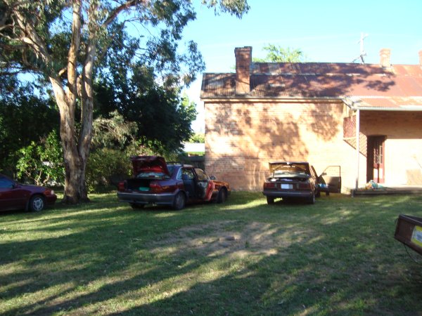
Figure 8: The author's two testbed vehicles for assessing the rig's portability, Beechworth, Victoria, Australia
Object Metadata
The imaging revolution has come with certain costs. One is an avalanche of image data. New scanning and digital capture devices capture several times more data than earlier generations of photographic imaging devices. 3D digital imaging of artefacts using V3D generate several sets of metadata. Each digital image generated by the V3D has its own set of source data. These data provide information about the creation date of the image, resolution, digital camera type, etc.
An extract from a raw data file shows lens metadata:
<exif:FocalLength>30500/1000</exif:FocalLength>
         <exif:FocalPlaneXResolution>1090370/292</exif:FocalPlaneXResolution>
         <exif:FocalPlaneYResolution>817777/219</exif:FocalPlaneYResolution>
         <exif:FocalPlaneResolutionUnit>2</exif:FocalPlaneResolutionUnit>
         <exif:SensingMethod>2</exif:SensingMethod>
         <exif:FileSource>3</exif:FileSource>
By employing Photoshop (or similar applications) to view the file metadata, one can read embedded camera source data that are sufficiently detailed and provide an important record of camera settings, concerning capture, import and resolution. The V3DOR itself can provide additional metadata (see Figure 5, the Rig GUI). All camera positional and rig incremental settings can be incorporated in QTVR descriptive metadata. There is still much work to be performed in respect of additional specific metadata sets in descriptive, structural and administrative categories for V3D applications that include provenance and contextual information about the object itself and the capacity to link it to associated metadata records, such as other images, photographs, et cetera. Common and flexible file formats for archiving and disseminating V3D/3D stereoscopic scans in the museum and academic teaching sectors are yet to be agreed upon [11].
Current and Future Developments
A manually controlled parallelogram-type camera mount device with the function of accurately displacing the camera by an adjustable distance (human eye-separation) for stereoscopic imaging has been trialled. Servo-equipped automation has also been considered, but the advent of digital 3D stereoscopic compact cameras has led to the postponement of this sub-project until these cameras can be fully tested. Trials are underway with a recently released Fuji 3D W3 digital compact camera mounted on ORm1 with the intention of capturing separate (displaced) images at each camera rest-point. Stereo-pair hybrid synchronised QTVR .MOV images will be displayed on a 3D monitor requiring the viewer to wear 3D stereo glasses. It has not been found that stereoscopic 3D has been combined with QTVR-type Virtual 3D photography anywhere else for this purpose. Auto-stereoscopic monitors (glasses-free) manufactured by Magnetic 3D and NEC are being investigated.
We are further trialling infra-red and ultra-violet illumination of artefacts, although recent developments in multi-spectral and hyper-spectral imaging (using fixed- or tunable-frequency-band filters), as used in the analysis of the Archimedes Palimpsest [12], have perhaps more cost-effective useful applications in our work. A means of 'piping' full-spectral sunlight into subterranean caverns in institutions would need to be devised if imaging could not be performed above-ground.
The use of a rigid background (of a suitable colour) attached to the camera arm counterweight (opposite the camera) is being investigated. Possible difficulties are background area size (in order to maintain complete background coverage using different camera lenses) and the rigid background frame limiting camera arm travel. If proven feasible, a framed background opposite the camera would produce further savings in time.
Conclusions
Our V3D Object Rigs have been realised thanks to following a multi-disciplinary approach to imaging hardware and software development. They have brought 3D imaging and colour recording technologies together to develop a Web-viewable system for QTVR records of cultural objects. They have added to the repertoire of 3D digital imaging technologies that are significantly affecting the ways in which cultural artefacts can be understood and analysed - and how they may become integral to a range of functions, such as heritage documentation, exhibition, conservation and preservation. However, there are still barriers to this virtual engagement, including resourcing, time and costs. Although V3D/QTVR is not by any means a new technology, we believe our multidisciplinary approach has allowed significant improvements which maintain the position of V3DORs as useful, accurate, portable, inexpensive (and obviously non-contact) imaging devices. Their functionality is being extended with newer image capture devices, such as 3D digital cameras and tunable spectral filters. Furthermore, they can successfully act in parallel for cultural artefact imaging with more recent laser 3D surface imaging technologies [13].
It is apparent that visualisation tools such as the ORm2, especially when used in large-number artefact collections, have the ability to produce large datasets from similar object categories in this, as yet, not-quite-common V3D/QTVR form. We hope the ORm2 (and successors) will therefore become widely used instruments which will add much information to the 'data deluge' for which even newer digital tools currently under development will provide productive data access, data mining and thus might provide emergent, creative data analysis.
V3DORm2 will be brought to EVA London 2011 [14] in July as a conference demonstrator. If there is interest, it could be easily transported to other locations in the UK/Ireland for further demonstrations. A compendious Web site illustrated with many more images and including V3DOR, PTM, 3D Remote Instrumentation + in-field recording and high-definition 3D Telemedicine projects is soon to be published on the World Wide Web [15]. We hope to include full CAD drawings and details of construction materials and construction experience to allow others to replicate (and, we hope, improve upon) our various apparatus.
Copyright Note
Figures 6 and 7 have been chosen to illustrate some of the choices and processes to be used in QTVR-type image creation. Fully rotating V3D/QTVR images can eventually be found at the Web site location [15]. These images are copyright © 2010 Australian Institute of Archaeology and permission for re-use for purposes other than teaching or research should be sought from the author.
Acknowledgements
The author is grateful to Ann Borda, Dirk van der Knijff, Chris Davey and Monica MacCallum, amongst others, for their kind advice on the content of this article.
References
- The death mask and faces of Ned Kelly http://www.denheldid.com/twohuts/story10.html
- Kandel, E. and Schwartz, J. (2008) Constructing the visual image. In Kandel, E. and Wurtz, R.(Eds.), Principles of Neural Science, 5th edition. McGraw-Hill, New York.
- Helen Macpherson Smith Trust http://hmstrust.org.au/
- Galil Software http://www.galilmc.com/
- LabVIEW http://www.ni.com/labview
- The Australian Institute of Archaeology (AIA) http://www.aiarch.org.au/
- Victorian eResearch Strategic Initiative (VeRSI) https://www.versi.edu.au/
- e-Research, La Trobe University http://www.latrobe.edu.au/eresearch
- QTVR and Flash Object Movie Software - Object2VR - Garden Gnome Software http://gardengnomesoftware.com/object2vr.php
- Polynomial Texture Mapping | Wessex Archaeology http://www.wessexarch.co.uk/computing/ptm
- Beraldin, J.-A., National Research Council Canada: Digital 3D Imaging and Modelling: A Metrological Approach. 2008 in Time Compression Technologies Magazine, January/February 2008, pp.35-35, NRC 49887 referenced in [13]
- Archimedes Palimpsest Project http://archimedespalimpsest.net/
- Mona Hess, Graeme Were, Ian Brown, Sally MacDonald, Stuart Robson and Francesca Simon Millar, "E-Curator: A 3D Web-based Archive for Conservators and Curators", July 2009, Ariadne, Issue 60 http://www.ariadne.ac.uk/issue60/hess-et-al/
- 2011 home | EVA Conferences International http://www.eva-conferences.com/eva_london/2011_home
- 3D Visualisation Research (under construction) http://social.versi.edu.au/3d/
